Filament Guide/Sensor for Anet A8

Description
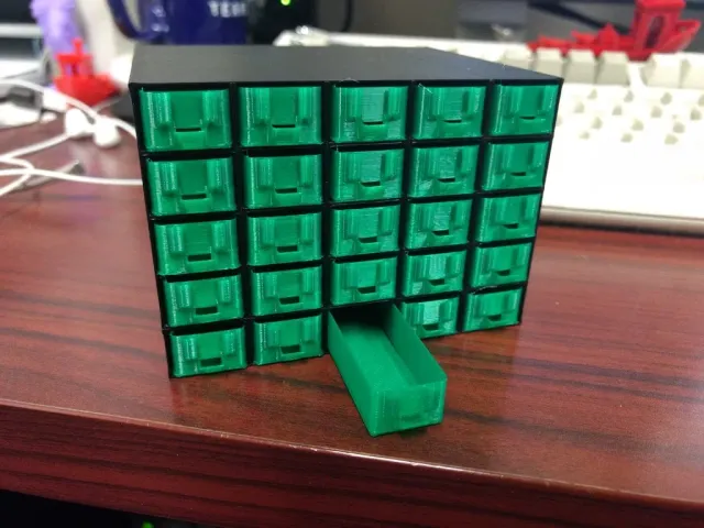
PDFUpdate: (29 Mar 18) I tried mounting the sensor shown in the photos this morning. It was a tight fit on the frame, but it worked. What didn't work so well was pulling filament through it when the extruder was at one end of the carriage or the other. The sensor really wants filament to pass straight through, with no bends nearby. A redesigned frame that holds the sensor higher and a smaller filament guide underneath that constrains lateral movement near the sensor might be in order.
I started with an existing sensor design and added on a small filament cleaner on the input side and an attachment point for a brace to hold it to my printer. To figure out the size to make the attachment point after I had printed the frame, I knocked together a simple filament guide that also fits the frame; even at 0.1 mm, it prints in just a few minutes so that I could tweak the size and reprint until I got the fit I wanted from it. Even if you don't care about the low-filament sensor, the guide-and-frame combo is an improvement over existing designs I've run across in that it's bolted to the frame and doesn't slide around.
The frame was printed at 0.2 mm with supports that need to be removed carefully. The other components are printed at 0.1 mm. If the frame is also printed at 0.1 mm, the filament-guide and sensor attachment points might be a bit oversize; the attachment point on the sensor has a hole for one of the setscrews left over from building the printer (will probably need to drill it out some more), or you could tweak sensor.scad to shrink the hole to match.
A8-0011.stl is included from https://www.thingiverse.com/thing:2288314 for reference purposes, but I found that the upper display mounting holes on my printer were higher than indicated and had to change my design accordingly.
Post-Printing
Connect two wires to the common and normally-closed contacts of a roller microswitch (I used this one: https://www.frys.com/product/2314479?site=sr:SEARCH:MAIN_RSLT_PG) and zip-tie them maybe an inch away from the switch for strain relief. Crimp 1-pin sockets (such as https://www.frys.com/search?search_type=regular&sqxts=1&cat=&query_string=wjw008) onto the ends and plug into ground and an available GPIO pin on your Raspberry Pi. Add and configure either https://plugins.octoprint.org/plugins/filament_sensor/ or https://plugins.octoprint.org/plugins/filament_sensor_reloaded/ to enable the sensor.
I needed to clip one of the tabs off of the sensor lid to keep it from interfering with the switch. There's also just enough wiggle room for the switch that it might not
Category: 3D Printer AccessoriesTags
Model origin
The author marked this model as their own original creation. Imported from Thingiverse.